Search This Blog

Monday, June 16, 2014

How to connect Bitx VFO with Ik3OIL FLL

Many friends had requested me to  show how the Bitx VFO could be connected to the Ik3OIl FLL counter to stop the drift in the Bitx VFO.

Presented here is a video and details as how to connect the Bitx VFO with the Ik3OIL freq counter.


First we present the video with the Bitx VFO that is connected with the Ik3OIL Freq counter.
The FLL control circuit works with combination of some components and software on the counter and some parts are on the IK3OIL VFO pcb. The main part being the BB204 varactor diode. A buffer stage has been taken from the Ik3OIL VFO pcb.

In this demo we powered the bitx VFO and the Ik3OIL Counter . You may observe that after the red led stops to blink the FLL takes control and stabilizes the VFO.
In the demo i have also rotated the main tune and fine tune capacitor which gives complete coverage for the 20mt band. There is no drift as the tuning is stopped and the FLL control takes the new readout and starts to control the VFO.

This demo has been done on the Bitx version 3 exciter.

I would welcome any one who wants any more help.


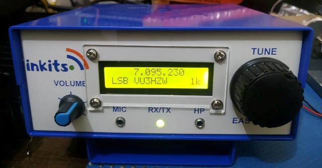
BITX VER 3 WITH Ik3OIL FLL CONNECTED


               IK3 OIL VFO PCB USED WITH THE SET UP


                        BITX VERSION 3 EXCITER PCB


                           FLL FREQUENCY COUNTER


  1. Some important points to be noted: 
  2.  In VFO use Polystyrene Or NPO capacitors
  3. Use RG174u for all RF connections
  4. 12 Volts can be taken to the FLL VFO pcb from the bitx power supply 


Monday, May 19, 2014

Stacked VFO coil for bitx3b vfo

Bitx3B VFO stage picture has been posted here. The Bitx3B VFO is made with two number's of
T37-6 stacked together and quick fix applied on it.

The trimmer at control of FLL will need to be engaged at such a point as to observe the least drift .
The VFO is rock solid and i did not find any drift .

The FLL menu switch has been soldered on the solder side of PCB, so that it could be easier pressing the switch while adjusting the BFO or VFO to set their frequencies.


Saturday, May 17, 2014

Bitx3B New built

Here are some pictures of my new built Bitx3B .  This new bitx3b set is built on the second batch of PCB for exciter which has some minor changes.
The VFO uses 2 number of T37-6 stacked . The results are very good. I could find no drift at all. very shortly i will publish a video on it. provision is also provided on the new board to add DDS if VFO is not to be used. And yes I have also installed the audio mute circuit in this set.

The power supply used is a 24 Volts 2.5 Amps SMPS Laptop power supply.
The RF output is 4 watts clean.


Power Supply 24 Volts SMPS from my Laptop

Thursday, May 8, 2014

Bitx 3B PCB second batch


  The second batch of Bitx 3b PCB now has the following changes from the first batch of pcb's made.

  1.  Q16 is not on the main exciter PCB now, instead we have a additional PCB of audio mute
      delay circuit. Please observe connections for integrating the connections from the schematics.

  2. Two components have been added in the mic pre amp. 100UH and .001 at the mic pre amp circuit.
     for better filteration of audio coming from the microphone.

  3. Two pin connector's  point has been added at 
      a.  VFO for DDS optional use.
      b.  Audio to agc circuit
      c.  LM386 Audio Mute point taken to the Audio Mute PCB

Some Important Points:

1. We recommend the VFO coil to be wound with 2 nos of T37-6 stacked with about 40 turns plus or minus a few turns, for more stable VFO.  The coil has to be glued with quick fix for better stability.
The second recommended VFO coil is on T50-2.   Single coil. Both work as very stable VFO's

For Drift:

The VFO has two trimmers. The first towards the VFO coil is for fine tuning your VFO if your VFO coil is short of turns, so by adjusting the trimmer you can set the frequency of your VFO.

The second trimmer that is connected with the CONTROL circuit of FLL counter is the most important as te setting of this trimmer will determine the stability of your VFO. The trimmer has to be engaged in such a way as to observe no drift, if you see your vfo drifting tune the trimmer at such a point where you observe the VFO becoming stable, that is the correct setting point for the vfo's stability. The FLL has to be connected with RG174u cable for input to counter and the control point.


Featured Post

   My Journey with Amateur Radio: Sunil Lakhani (VU3SUA) Shares His Story Hello, fellow radio enthusiasts! This is Sunil Lakhani, also known...