Search This Blog

Monday, March 28, 2016

New Kit: JBOT HF Linear Amplifer

After a gap of long time I have been able to bring out a new kit, from our most popular author Ashar Farhan's collection. Yes its the JBOT kit.

The JBOT has been tested on our designed PCB and works extremely well.
We have used 2N2218, earlier we used 2N2219 which had an higher gain and was giving some problem, but we have found 2N2218 more suitable and also as suggested in JBOT article.

We got a pack of 500 transistors 2N22I8 and so we are glad that we can offer transistor that have  been tested and do not oscillate.

We changed just 2 resistors value  as per the need of the gain of the transistor, and the complete kit was build as per the article.

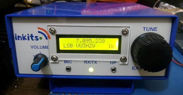
Kindly find pictures attached below:

JBOT HF Linear Amplifier 

JBOT HF Linear Amplifier kit

Printed Circuit Board JBOT Front

Printed Circuit Board JBOT Rear
This kit can be purchased from our ebay store.

Buy JBOT kit from our store

Only Available in Kit form.


Friday, January 29, 2016

Upgrade of website AmateurRadioKits.In

Recently we moved our website to a new server, this had to be done for providing our friends a

better view of our products and all the documents for our kits,which are  to be published on our web

pages for a live preview and download. If you wish to purchase our Bitx or other kits,  then kindly do so

from our ebay store Fusion Radio VU3SUA

We are working to make this website more pleasant.

We shall be opening the complete website very soon.

Have a great day…..

Friday, January 15, 2016

New Pictures from OM Arek SO5HMI Bitx3C


The earlier pictures of Bitx3C sent by OM Arek from Poland were without the complete wiring etc, so I had requested Arek to send me some of his Bitx3C pictures with complete built up set. 
So now we  have received some nice complete built up  pictures of Bitx3C ADE-1  from OM Arek    SO5HMI   .
Enjoy them. The construction is excellent so as the working set Arek.....Many Many DX with your Bitx3C ADE-1 

BITX3C 20 MT 

BITX3C WITH ADE-1 

BITX3C Arek SO5HM

BITX3C FROM POLAND

Saturday, January 9, 2016

Bitx3C From Poland

Recently there has been lot of Bitx building activity from Europe ,radio  amateurs from Russia, Poland ,France And Germany are building the Bitx3B and Bitx3C.
We have received some nice build pictures of Bitx3C ADE-1  from OM Arek    SO5HMI   from
Poland. Congratulation to Arek for completing his Bitx3C and also helping his friends build the Bitx.

Here are some pics as below sent by Arek for Bitx3C ssb tcvr with ADE-1 mixers

BITX3C By Arek SO5HMI 

BITX3C WITH ADE-1

BITX3C VIEW


Arek has also uploaded a Video YOU TUBE for his Bitx


Keep watching have fun, we shall bring in more news about some new developments with our new
Bitx kits. 

Saturday, November 28, 2015

Bitx Case In New Colour And Models

We are trying to bring some new colours and models for Bitx Case .

One of the new colour is  Black And Silver , this is available in two models, the first one is

the Bitx case with additional provision of Menu switches. So now the FLL counter swithes can be mounted on the Front panel of case.

The second model has the facility of mounting DDS function switches on the Front panel. The Encoder is fitting on the Tune control.

We shall be also offering a DDS very soon, that will fit on this Bitx DDS Case.

Bitx 3B/3C Black And Silver Case With Menu Switches For FLL


Bitx 3b/3C Black And Silver Case With Switches For DDS Functions.


Monday, September 7, 2015

Bitx Version 3C SBL-1 With DDS

As promised earlier I am publishing some pictures of the Bitx3C SBL-1 with a DDS for 20mt band.
The set is working absolutely fine with good receive and transmit of 7 watts.

This present set is mono band, but the idea was to use a DDS and also provide DDS with the Bitx 3 kits.

Bitx Version 3C SBL DDS 

Top View 

PA Bitx 

DDS And AGG 

Bitx3C SBL-1 Exciter 

Very soon video of Bitx3C SBL-1 with DDS will be put up on this site and You Tube.


Tuesday, August 25, 2015

AGC Bitx

In our earlier pictures for the AGC module, there was a connector placed in a wrong direction and also the trimmers were placed in the opposite direction.

We are publishing the correct placement again for the mentioned items.
Some care is to be taken in  handing the VU meter as it is quite fragile. Instead of soldering the pins of VU Meter to the AGC pcb it would be better to solder short piece of wire pair and connect to the AGC pcb.

The audio mute pcb is overlapping the PA pcb this happened as the PA pcb was modified for the diode RXcut off switch, suitable spacers can be provided to raise the hight of the audio mute pcb while fixing on the case.


Featured Post

   My Journey with Amateur Radio: Sunil Lakhani (VU3SUA) Shares His Story Hello, fellow radio enthusiasts! This is Sunil Lakhani, also known...