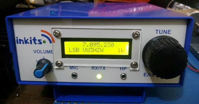
Bitx3B VFO stage picture has been posted here. The Bitx3B VFO is made with two number's of
T37-6 stacked together and quick fix applied on it.
The trimmer at control of FLL will need to be engaged at such a point as to observe the least drift .
The VFO is rock solid and i did not find any drift .
The FLL menu switch has been soldered on the solder side of PCB, so that it could be easier pressing the switch while adjusting the BFO or VFO to set their frequencies.
Search This Blog
Subscribe to:
Comments (Atom)
Featured Post
My Journey with Amateur Radio: Sunil Lakhani (VU3SUA) Shares His Story Hello, fellow radio enthusiasts! This is Sunil Lakhani, also known...

-
My Journey with Amateur Radio: Sunil Lakhani (VU3SUA) Shares His Story Hello, fellow radio enthusiasts! This is Sunil Lakhani, also known...
-
After the Bitx3C ADE-1 we present the Bitx3C SBL-1 . The schematic is being published here. The Bitx3C SBL kit will be soon available ...
-
NEW VERSION OF BITX KIT AVAILABLE After a break of few years we are back with our new Easy Bitx Kits. The Easy ...


.jpg)
