


An Error has been found in the frequency counter pcb design by VU3WJM . The errror has been found in the five digit mode LSD and MSD,which have been swaped,that is the display on the left the one driven by NPN transistor should have been the LSD.
New PCB for counter will be available soon with the rectification of error. Meanwhile friends who
have already got the freq counter PCB could correct the error by swapping the FND connections going to the cathode of the 5 FND.
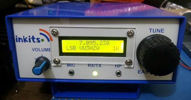
Our friend Jean Scott F1BGY has sent pictures of his frequency counter with the jumpers
swapped in the correct position. "Thanks Jean for the beautiful pictures of your frequency
counter."


.jpg)
