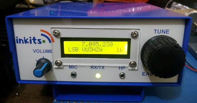
Contents of Email from DG1NPJ Juergen Pfeifer From Germany
Hi Sunil,
the CW Modul i have found by Google looking for schematics of Bitx20, it works, but the Audio Output is to small, i will fix this bug in the next days.
the AGC schematic is from the Bitx Yahoo Group, the Soundcard Interface is a old schematic, it works on all my TRX in my shack. The Pic Keyer i have found on this webpage: http://freenet-homepage.de/
For the AGC/Keyer and CW Modul i send you a PCB Layout, not the best but for me is good.
The connect of the FLL VFO is on my Bitx Q6 Emitter ( no Transitor) to Condensor Basis of Q7.
It works great wenn you make the coil L1 in VFO with 50 Turns (Frequency 14.065 to 14.350 MHz )
for CW i put a Resistor with 18 K from BB204 ( D1 and D2 ) with a switch to GND ( Frequency 14.000 to 14.075 MHz )parallel to R3 82K.
The same switch i use for CW Tone or PSK (from Soundcard Interface ) on Mike Input.
The S meter, the PCB is from you, is connectet in the AGC on R12 of 12 V side, it works but its only for viewing :-)
not a real meter !!
My PCB are made only with a Laser Printer on Paper and Transfering with a hot Iron on the Copper befor etching.
Cheap and Good , Look here: http://thomaspfeifer.net/
Ist only the same Name of this People its not my brother hi hi
Side Tone Oscillator For Bitx CW Mode
AGC And CW Keyer Schematic for Bitx
Hope the info is useful for friends to get the Bitx on CW and digital Modes.
The above PCB for AGC and Keyer will be ready soon and made available
73's
Sunil Lakhani
VU3SUA


.jpg)

No comments:
Post a Comment