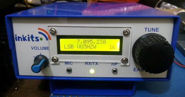
To make it helpful for all building the Bitx version 3 I am posting these pictures here and feel
very grateful for the contribution and a fantastic effort by Om Leonard.
BITX UNDER LENS OF LEONARD
Bitx20 Version 3
After building a Far Circuits Bitx20 and a Hendricks's QRP Kits bitx20a kit, I decided to build another bitx after seeing this posting:
A new batch of Bitx PCB, in glass epoxy ,masked, roller tinned and with
component place-ment is in ready stock for delivery world-wide.
Also available is the pcb for Avala 01 Sdr monoband tcvr.
I am giving a very special discount on the pbc's. To know further about
the discount, kindly send me a mail at suillakhani123@ gmail.com
I sent off my email and received this back:
Dear Leonard,
The Bitx Version 3 PCB is for $10 PCB +Coils+1 No 2570 transistor.
The Avala sdr pcb is for $5.Shipping is extra $ 10.
I looked at this web page to get an idea what the Avala sdr was and decided that I couldn't pass up a deal like this.
After a trip to paypal, the boards for the bitx and the avala were ordered. Soon I received a package in the mail. In it was 3 pcb's. This was the bitx board along with some of the specialized parts. The other boards were the PA board and the Avala board,
There was enclosed, a schematic, a component layout, and a few other pages of documentation.
After examining them, I decided to make an "exploded" layout drawing using a section-by-section approach to the assembly and testing. I will function test each section as it is assembled. This will almost insure that the board will function when everything is completed. I already had an head start on the project as this would be the 3rd Bitx I had built. I already knew what the signals should look like in each stage.
I decided to start with the antenna end and soon I had the following parts placement diagram for the bandpass filter section.
Next I assembled it and connected a sweep generator to the input and my oscilloscope to the output.
After a little tweaking, this was the final result. The scope is displaying from 10mhz to 20 mhz. Each division is equal to 1mhz.
Rf Driver Section
Following my plan to work from the antenna back, the next section was the RF driver stage. It was the next logical section of the board to populate also.
With the drawing done, the next step is assembly, then add a little power, no smoke, that's good, and a signal input.
Then on to test with the scope. 100mv 14.2mhz in, 1.5 volts out. That was open circuit and we probably won't get that when we hook to the PA, but for now, thats a gain of 15. On to the next stage!
The VFO section stands on it's own and will be easy to test so I choose that as the next section. A transformer was furnished with the boards but it would have to be rewound as the VFO needed about 9uh's of inductance and the transformer maxed out around 5uh. Depending on the variable capacitor you tune with, the turns on the inductor may have to be adjusted but 50 should be plenty and then you can remove some to adjust the frequency up. My test capacitor tuned from 15-377pf and the VFO had almost a 500khz tuning range so setting the frequency shouldn't be really critical. I didn't tweak the range on mine as I will do that when I install it into a case.
Next I assembled it and connected my oscilloscope to the output. You can see the power connection for the test
I checked it out with the scope. A little over 3.5 volts. This will be less when the transformer is hooked up due to it's loading. There is some distortion of the sine wave so we know there is some harmonic content.
A quick look with the spectrum analyzer to see what the 2nd harmonic looks like.
1 Mhz/div horizontal. The left is 0hz and the right is 10mhz. Each vertical division is 10db. It looks like the 2nd harmonic is down about -25db.
Time to drink a cool one and then pick a new section to do next.


.jpg)

No comments:
Post a Comment