Search This Blog

Monday, April 14, 2014

Bitx3B VFO

The FLL frequency counter used for Bitx3B may sometimes not read the frequency from the Bitx3b VFO stage, the reason being the VFO buffer has a low output kept for the stability of the VFO. It is observed that in some cases the Freq counter does not read the freq and some times it does, some transistors may have a higher gain and some lower as the brand is not same for all the kits we supply the 2n3904 transistor. Due to the different gain of transistor the issue of FLL not reading the freq arises.

 The solution is simple without disturbing the VFO capacitors value's we just need to change C13 in the FLL Freq counter from 22PF to 47 PF. I tied this and it works fine. Here is a picture of FLl Freq counter with FLL C13 that has to be changed to 47PF


The second issue of VFO Freq Stability. T50-6 was tried on the VFO of Bitx3B with around 50 turns. Kindly adjust turns to reach 4.MHZ reading on the VFO, you may have to wind turns as per need, if you connect the FLL freq counter you could wind the turns with out much trouble.

I  must admit that T50-6  is much much better with no drift at all. in the VFO.  I was able to have a qso with VU2YK on this Sunday for more than 15 minutes with a very stable VFO with zero drift  . 
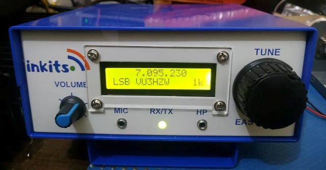
Also I took a video of Bitx3B showing the freq stability. This Video taken with the antenna not connected, just to check the VFO on power on.

The VFO works okay also with the T37-6 with very less drift but was found better with T50-6. Next experiment is to try 2 nos of T37-6 stacked together. I shall publish the result soon.

Thursday, April 3, 2014

Explanation of how the delay circuit works.

Om Blake Bartosh has shared with us the explanation as to how the delay circuit works as you may be eager to try it out on your Bitx. The Audio Mute circuit operates in the following way. The 555 timer is connected to the PTT switch and generates a 100 msec pulse when PTT is engaged and another 100 msec pulse when PTT is released. The 555 timer is configured as a debounce circuit, so contact bounce of the PTT switch does not initiate any new pulses. The output of the 555 timer and the PTT switch signal are combined in logic to form two signals, a mute command and a transmit command. The mute command turns on Q16 of the Exciter board which shorts the audio signal to ground, and no sound is heard from the speaker. The mute command occurs immediately upon engaging PTT, but the transmit command is delayed by 100 msec. This delay ensures audio transients due to switching from receive to transmit mode do not cause a "pop" in the speaker, but is not so long as to be noticeable to the operator. The transmit command energizes the relay coil of K2 of the PA board via a 2N3904 transistor and the rig switches to transmit mode. Upon releasing PTT the transmit command is immediately turned off, K2's relay coil is de-energized and the rig reverts to receive mode. 100 msec later the mute command is turned off and the speaker is activated again. The Audio Mute circuit is powered by 12V+, and a voltage regulator reduces the 12V+ voltage to +5VDC required by the 555 timer and the 74LS00 quad NAND gate IC.

Monday, March 31, 2014

Bitx3B VFO

The Bitx3B has a Varactor tuned VFO using MV209 and the stability is controlled with the Ik3OIL FLL Freq counter which has an inbuilt software to correct the drift in the VFO.

Building a stable vfo is an art and if not built correctly it would not perform optimum.

Picture and Video  below outlines some important factors that could enhance the performance.

BITX 3 B VFO SECTION

Outlined below are some points that need to be performed on the VFO section of Bitx3b for a drift free VFO

1.  VFO Capacitors to be NPO or Polystyrene

2. L5 VFO coil to be wounded tightly, placed flat on board and   applied  with thin layer of glue, quick fix is preferred as it has a thin layer, not very much to be applied, just enough to cover it.

3.MV209 And BB204  legs to be trimmed so that they may be just about near the board and soldered. A thin coating of quick fix could be applied on their sides, this way it becomes a sealed unit and gets protection from any air currents to extremely temperature.

4.It is better to use X position with 0.1uf  preferred Silver Mica /NPO or Polystyrene capacitor.  If you place a jumper across X then you may experience some drift, with 0.1uf in place the drift is manageable with the FLL counter attached.

5.  For FLL Freq counter Input and Contol it is recommended to use Rg174u coax

 6. Adjustment of Trimmer on control side of FLL is very important. The trimmer on extreme end of board is the trimmer that connects to the FLL control unit. Remember to fully mesh the trimmer or the vfo may drift.

The vfo was tested using the above recommendations and the test results:  2 Hours VFO On with max drift of 25Herts 


Sunday, March 30, 2014

Audio Mute Circuit For Bitx

Bitx had a problem of  noise being generated on pressing the PTT button. The usual way of muting the PIN 3 of LM386 did work  to solve the problem much, although to some extend, while working with Bitx3b i had discussion regarding this problem with Om Blake Bartosh from USA who was also building the Bitx Version3b  and who has also put in a great effort in bringing out the new Bitx3b construction manual.

The idea was to make a project to mute the audio of LM386 completely.
Presented below is a schematic of the audio mute circuit designed and tested by OM Blake Bartosh.

I myself build it and its working perfectly with my bitx3b. This circuit can be used for any tcvr.
The complete assembled kit will be available very soon.


                                           SCHEMATIC OF BITX AUDIO MUTE CIRCUIT                          


                                           VIDEO OF BITX AUDIO MUTE CIRCUIT                          


Featured Post

   My Journey with Amateur Radio: Sunil Lakhani (VU3SUA) Shares His Story Hello, fellow radio enthusiasts! This is Sunil Lakhani, also known...