Search This Blog

Wednesday, February 10, 2010

Bitx Version 3 For 20 ,40 And 80 Mt Bands By Ross Bell VK3BEL

 
Bandpass Filter PCB


Low Pass Filter PCB And LSB /USB PCB

Our Australian friend Om Ross Bell VK3BEL is doing wonders with Bitx Version 3.

Ross likes keeping his Bitx simple and as original design, that is without a digital readout.

Ross has successfully made the Bitx for 3 Bands presently that are 20 and 40  and 80 Mt Bands, with modules provided by us for LSB/USB Change, which is a small pcb mounted above the Bitx Main Pcb BFO.

The second PCB is the Bandpass Filter, that is made for 2 Bands and additional PCB can be added for extra bands.
The third PCB is for the LPF also for 2 Bands.

We also have a PCB for using in Crystal Filter that can be used for Changing Filter For suitable use, ie CW.

We are publishing pictures and statement on Bitx  Version 3 for 3 Bands use as per Ross Bell.

Suggestions And Comments as per OM Ross Bell VK3BEL 

The bandpass coils were all wound with #39 wire on the same as the
20mtr coils supplied, a fiddly job.
for 40 mtrs 18 turns / 3 turns with the capacitance values being 82p
in parallel and 8.2p in series with the coils.
for 80 mtrs 21 turns / 4 turns with the capacitance values being 270p
in parallel and 22p in series with the coils.
For the VFO ,I multi tapped the tuning inductor for the required
2.7-3mhz ,4-4.5mhz and 6.2-6.5mhz,  75, 51 and about 28 turns for all
the bands.
To set up the bandpass filters, i connected them with coax to a
receiver and tuned the coils for maximum signal on the required bands,
only a small adjustment was needed after installing in the bitx.
It is great to have 3 bands, always a signal.....
great fun...
Thank you...


Hi,
I replaced all vfo caps with npo's , waxed the coils to the pcb and
also found the replacement of the zener with a 3 terminal regulator to
be much better frequency stability.I also placed a copper shield
around the vfo and the stability is good. I use the set all the time
and plan to go portable soon. all three bands are working well.

************************************************************************************

Well we thank Ross Bell for his Bitx Version 3 operating on three bands and wish Ross all the best for his Bitx version 3 for other bands too. :)  Cheers!

ALL DUE CREDIT TO OM TONY FROM UK FOR PROVIDING DESIGN FOR BITX ADD ON MODULES
Friday, January 29, 2010

Adjustments for S.Meter


Adjustments For S.Meter For Bitx  As sent by 
I0VBR Vittorio Bruni

  1. Solder all components to PCB
  2. Connect Potentiometer 470K to Audio in Bitx Volume Control. 10K
  3. Disconnect Antenna to regulate the adjustment for Potentiometer 470K, to Zero for
least deviation of the needle of the meter. It needs to regulate to the position where the needle extends as soon as to move itself
Finally connect antenna and adjust 100K Pot to S9 on a strong signal of 50uv to the antenna entrance

Thursday, January 21, 2010

Bitx 3 Mono Bander 7 & 14 Mhz By Om Ross Bell VK3BEL

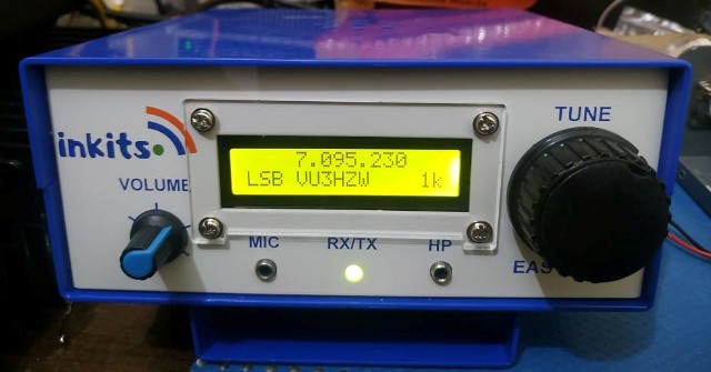
We have our latest Bitx Version 3  pictures coming from Australia sent by OM Ross Bell VK3BEL .
Ross has done an extreme good job in making the Bitx 3 for 2 bands 7 and 14 Mhz and he plans to make
it for 3.5 Mhz also . Ross had purchased the Bandpass  and low pass PCB from us and he is the first one
to use them . As more details come in from Ross I will keep posting for all friends.

Ross has already had a few contacts with his Bitx. He has some drift but that would be solved by using NPO capacitors in VFO.

Here are the pictures of Bitx Version 3 By OM Ross Bell VK3BEL

Great Looks 

 
Smart Building


Its Here Bitx 3 Mono Bander 7 & 14 Mhz

Wednesday, January 20, 2010

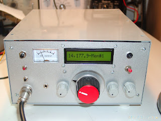
Bitx Version 3 New Look . Build By Om Ron Nesler W4DNQ

After getting the case made for Bitx Version 3 and  shipping some case's world wide , now we have some great pictures being sent by our friends.

These  pictures are  sent by Om Ron Nesler W4DNQ with Bitx Version 3 in the case shipped by us.

We thank Ron for being kind to share his pictures and we also compliment him for making the Bitx 3 in such a short time.

Ron has made use of   DDS by N3ZI Kits.  It looks great. Ron is still working on the RF Gain and Filters which he plans to install soon.


          PICTURES OF RON NESLER'S  BITX  VERSION 3


                                        Bitx Version 3  Build By  Om Ron Nesler W4DNQ


Inside View Of Bitx Version 3 . Great Construction.


                                          Inside View Bitx Version 3 . Close View

 
 Bitx 3 Case has a Fan. S.Meter,LCD Display and Speaker Mounting facilities.

 
                Bitx Version 3 look . Fan.BNC.On/OFF Switch.Morse Key Provision.

 
              Bitx Version 3 In A New Look : )   RON NESLER W4DNQ  BITX 3

More interesting news  will be coming in, as some club's are making the Bitx 3 as club project.

I will update on these news soon.

Best of 73's

VU3SUA

Sunday, January 17, 2010

Bitx Version 3 Case Pictures

Pictures of the Bitx Version 3 Case are being published here to give a better idea how the case looks like.
The case in in metal G.I and in a combo color combination and complete single color grey will also be available.


Saturday, January 9, 2010

DDS Version 4 Build By G6AJW Dave Lucas G6AJW

Direct Digital Synthesizer VFO For Bitx
By C.V.Niras/VU3CNS
cvniras@hamradio.in 

The Project is publised in hamradioindia website


The DDS Version 4 is an excellent project for using with any tcvr. Many Ham's are now purchasing the PCB and building the DDS 4 Project.


.
PIC16F628A and AD9850 or AD9851. PIC16F628A is an 18-Pin microcontroller
with 2K byte program memory, it is a FLASH-based and a member of the versatile PIC16F62XA family of low-cost, high-performance, CMOS, fully- static, 8-bit microcontrollers. PIC16F62XA devices have special features to reduce external components, thus reducing system cost, enhancing system reliability and reducing power consumption.

Features
1. Range 0 to 70 MHz by 1 Hz step.
2. Freq setting in 1, 10, 100Hz, 1, 10, 100KHz, 1, 10 MHz by using a low
cost mechanical encoder with a variable tuning rate. 3. 2 rows X 16 character LCD display.
4. A 4 x 3 Keypad used for easy freq entry.
5. IF, CW, SSB offsets settings when used with Transceiver/ Receiver. 6. Software calibration to WWV or equivalent. 7. Two VFOs and split freq operation.
8. 19 user memories, memories freq + mode (i.e. LSB/USB etc.)
9. All settings are held in EEPROM and are permanent (but user can
change it any time).
10. 4 Band selection and 4 Mode selection outputs.
11. When operating below IF frequency, clockwise rotation of rotary
encoder decreases DDS out put frequency but increases the display frequency.
12. RIT operation.

The PCB for the above project were designed by Tony Fletcher of UK and also mentioned earlier on this blog. Since then many have build the DDS. Hopefully we will be publishing the info as how the DDS
work's with the Bitx, but it is a complete solution for a multi band Bitx.

The Latest to build the DDS 4 is G6AJW  OM Dave Lucas from U.K who has very kindly granted me permission to publish pictures of his build DDS 4, he is also going to make the Bitx Vr 3 and hopefully very soon he would let us know as to how the Bitx 3 works with DDS Version 4.

 Here are the pictures of DDS 4 build by  . Dave Lucas G6AJW.


    Length= 203mm height =76 mm width =152mm


   Inside View of the constructed DDS VER 4


  Front And Side View of DDS VERSION 4


     DDS VERSION 4  Build BY Dave Lucas .


Thursday, December 31, 2009

Featured Post

   My Journey with Amateur Radio: Sunil Lakhani (VU3SUA) Shares His Story Hello, fellow radio enthusiasts! This is Sunil Lakhani, also known...